This article is divided into 2 parts interfacing of 16x2 LCD with 8051 microcontroller and working methods of LCD.
Here is the program for LCD initializing with 8051.
 |
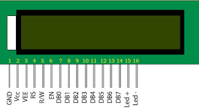
| 16x2 LCD |
Pin 1-2 : are used as the supply to LCD
Pin 3 : is used for adjusting contrast of LCD. Vcc is given through a potentiometer and by varying resistance in potentiometer, input voltage to pin 3 can be varied (using voltage divider formula to potentiometer) resulting in changing contrast of LCD.
Pin 4 : RS pin is register select pin used for selecting modes between instruction mode and character mode. When RS pin is connected to ground, instruction mode is on and when RS pin is connected to Vcc, character mode is on. In instruction mode, micrcontroller sends 8 but signal. This signal is treated as instruction (e.g. clear screen, turn on LCD, turn off LCD etc). In character mode, microcontroller sends signal which is treated as ASCII value and corresponding character is printed on LCD display.
Pin 5 : When R/W pin connected to ground, write mode is selected. In write mode characters are written on LCD. When R/W pin is connected to Vcc, read mode is selected in which is used for reading character on LCD.
Pin 6 : EN pin is one of the most important pin of LCD. When we give a pulse to EN pin, after the falling edge, instruction is executed or character is printed on LCD depending upon RS pin. Hence for writing every character on LCD or for executing any instruction, we first require EN pulse,
Pin 7-14 : D0 to D7 are the data pins through which we can send signals for instruction or character.
Pin 15-16 : LED+ and LED- must be connected to Vcc and ground respectively to turn backlight of LCD.
There are 2 different modes in LCD. One is 8 bit mode and another is 4 bit mode. In 8 bit mode, we send 8 bit signal to LCD. In 4 bit mode, we first send higher 4 bits of 8 bit signal to D4-D7 and then after another EN pulse we send lower 4 bits to D4-D7. Hence in 4 bit mode, D0-D3 aren't used. They are connected to ground. LCD will work in 4 bit mode or in 8 bit is decided by configuring LCD through some commands in initialization process of LCD.
- Interface of 16x2 LCD:
- Connect GND to 0V and Vcc to 5V.
- VEE is connected to middle pin of potentiometer when other 2 pins of potentiometer are connected to Vcc and GND. To get maximum contrast connect it to ground.
- As we require both the modes, instruction and character, we need to change RS pin runtime. Hence connect it to microcontroller and change the state of RS whenever required through program.
- If your project requires only displaying characters on LCD then connect R/W pin to ground or connect it to microcontroller and change modes whenever required.
- As we need to send pulses to EN pin, connect it to microcontroller.
- For 8 bit interfacing, connect D0-D7 to microcontroller and for 4 bit interfacing, connect D0-D3 to ground and D4-D7 to microcontroller.
- Connect LED+ to Vcc and LED- to ground to turn on backlight of LCD.
Interfacing for 4 bit will look like following figure.
 |
| LCD interfacing |
Note: In proteus, LM016L character LCD do not require backlight pins. Backlight is turned on for LCD.

No comments:
Post a Comment